18-348 Lab #5
Spring 2015
NOTE: Lab 5 consists of two components (Lab 5 Part A and Lab 5 Part
B).
Relevant lectures:
- Part A: Lecture 8. Memory and Memory Bus
- Part B: Lecture 9. Economics and Code Optimization
Links to all files referenced in the lab and prelab can be found in the
Files section at the end of this document.
Caution -- this lab has the most challenging hardware construction portion
of the course -- start early on building your hardware!!
Pre-Lab 5 - Part A:
Goal: To familiarize you with the operation of a bidirectional memory
bus.
Discussion:
A bidirectional memory bus provides an interface between a CPU and a block of
memory. It is bidirectional because it allows the CPU to both write values to
the memory and read values from the memory. The bus is operated using a pair of
control lines - the Addr.H/Data.L line and the Write.H/Read.L line. Asserting
Addr.H indicates that a memory address is being driven on the bus, while
asserting Data.L indicates that data is being driven on the bus. Asserting
Write.H indicates the CPU is driving data on the bus to write a memory address,
while asserting Read.L indicates the CPU will read the data asserted on the bus
by the memory or I/O device.
- Consider the memory bus schematic
and the timing diagram below to answer the questions. If you need to know
how a specific part of the circuit works, refer to the corresponding data sheet
for that part. Data sheets are listed in the Relevant Reading section below.
- For the timing diagram, assume that all timing requirements (e.g., setup
time) are met.
- Our circuit emulates a memory bus and two memory-mapped I/O ports. We have
an 8-bit bus. Our memory space has an 8-bit address space and stores 8-bits of
data at each address. However, to keep the hardware simple for you, only one
address is available for reading ($9C) and only one address is available for
writing ($CC). (I/O ports are often are read-only or write-only, so this shows
you one way to set up such ports.) When we read from $9C, we read the value on
the 8-bit switch. When we write to $CC, we store the value on the LED display
and the LEDs display the inverted bit value as done in previous labs.
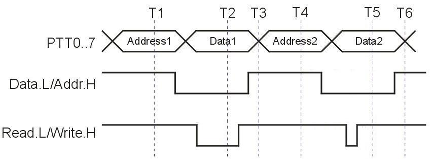
Figure 1: Memory Bus Timing Diagram.
Procedure:
None. This section only involves answering questions.
Questions:
For each question below, assume the memory bus is configured as shown in the
memory bus schematic.
1. For Figure 1, in 15 words or fewer per item, briefly describe what
is happening at each of T1 through T6, including whether that time instant is
part of a read cycle or part of a write cycle.
T1:
T2:
T3:
T4:
T5:
T6:
2. Suppose the current state of the memory is reflected by the values
in the table below:
Address
|
Value
|
$9C
|
$A4
|
$CC
|
Undefined |
We want to read the value at address $9C, then write the one's complement of
that value to address $CC. Based on this sequence, indicate the value on
the Address/Data bus at each time (use the values listed in the timing diagram
in Figure 1 above, e.g. Address1, Address2, Data1, Data2). Additionally,
indicate which element in the circuit is driving the value on the Address/Data
bus. You should refer to the chips by their designation in the schematic
(e.g. "U14" refers to the 74LS373 latch).
|
Value
|
Driving Element
|
Address1
|
|
|
Data1
|
|
|
Address2
|
|
|
Data2
|
|
|
3. Using the values you obtained in question 2, identify the values of these
internal lines of the memory bus circuit at the corresponding time instance.
(Note: we are asking for the pin output values, and not the value
"inside" the register if it isn't being driven onto the output pins.)
Use a hexadecimal notation to indicate a range (0 is the LSB). For
example, if Q7, Q6 and Q3 are 1 and the rest of the values are 0, then the
value you would enter is "$C8". Use a "Z" to indicate
high-impedance/disabled output. Use an "X" if the value is unknown,
such as when it depends on operations that occurred before the timing diagram
started.
Time
|
U14 Q7:0
(Address Latch) |
U9 Q7:0
(Data Register) |
U7 B7:0
(Read Buffer) |
T1
|
|
|
|
T2
|
|
|
|
T3
|
|
|
|
T4
|
|
|
|
T5
|
|
|
|
T6
|
|
|
|
4. (Bonus) Submit a revised schematic that shows the setup for decoding the
addresses $A3 for read and $B3 for write. Include only connections to U14, U10,
U11, U16A and U15A -- you can omit the rest because they should be the same. If
you have to add an inverter or two then do so. NEATLY hand-drawn
of just those chips and their connections and scanned is OK. Better is probably
to edit or draw over the existing schematic. (For example, white-out
connections and draw new ones.)
Pre-Lab 5 - Part B:
Goal:
- To understand how to take advantage of the HC12 compiler optimizations and
restructuring C code to improve code execution speed.
Discussion:
The function of a compiler is to translate high level code (in this case, C
code) to assembly. In order to do this and do it efficiently, the
compiler must manage resources such as stack memory, registers, and code
allocation. But no compiler is perfect, and embedded system compilers are often
very far from perfect. You can help the compiler by writing code that it is
good at optimizing. In this lab, you will take a function which adds an array
of numbers and implement a new C language version of the function so that it
compiles more efficiently.
Procedure:
Part 1:
- Create a new C project. Be sure to include the Full Chip Simulator as
a build target. Download prelab_5b_skeleton.c. Rename it to
prelab_5b_andrewid.c (with your appropriate andrew ID) and replace the main.c
file in your project with it.
- Implement the ptr_add( ) function using pointer math instead of array
references. This course assumes you know C; if you are rusty on pointers a web
search on the keywords (C pointer tutorial) will reveal many sources of
information. (Note: you will have to comment out the function ptr_add2 for this
part to get the code to compile cleanly.)
- You are NOT permitted to use loop unrolling to speed up the
code. (Loop unrolling generally involves making copies of lines of
code to perform repeated operations in-line to avoid loop overhead. If you
aren't sure if you are doing loop unrolling, ask a TA.)
- Your code must work with any valid input and outupt parameters (e.g., with
an array that is a different size). You are NOT permitted
to modify the parameter inputs (the "signature") of the functions.
You are NOT permitted to directly access global variables
that might be passed to the routine, bypassing the parameter passing mechanism.
- Verify the compiler options. Select Edit > Full-Chip Simulation Settings from
the menu (you must have the full-chip simulator as the current target).
Navigate to Target > Compiler for HC12
. The value in "Command Line
Arguments" SHALL be "
-CpuHCS12 -D__NO_FLOAT__ -Ms "
- Run your ptr_add( ) function using the full-chip simulator. Verify
that it gives the same result as subscr_add( ).
- Use the simulator to measure the number of cycles the subroutine takes to
run. Your cycle count shall include all the compiler-generated setup and
cleanup code The simplest way to measure this is to place a breakpoint
in the C-code at the function call, record the initial cycle count value, then
Single Step Over (F10) the function
call. For full credit, optimize the subroutine code in C so that it
executes in fewer than 1560 cycles (this shouldn't be too tricky
if you use pointer code).
Bonus (Optional):
- For bonus credit, implement ptr_add2( ). You are NOT permitted to
use loop unrolling to speed up the code. (Loop unrolling is a valid
optimization in many contexts, but to keep this lab simple enough to fit within
available time and still teach the relevant concepts, we have to impose this
constraint on optimization.)
- For this part, you may make any changes to code and enable additional
compiler optimizations as you wish. Use the "
Options" button in the
Compiler for HC12 area of the
simulation settings (see step 3 in part 1).
- Run the code and verify that the results for ptr_add2( ) correspond to
those for subscr_add( ).
- Measure the cycle count to execute the function as described in step 5 of
part 1. To receive bonus credit, your implementation must execute in
fewer than 960 cycles.
Questions:
Note that all questions from this section MUST reflect the results you
obtain with the default compiler settings, as described in Part 1, Step 3.
- Record the values returned for each function and the number of cycles for
execution. For reference, the values for subscr_add( ) have been
included.
Function Name
|
Return value
|
# of cycles
|
subscr_add( )
|
15150
|
2236
|
ptr_add( )
|
|
|
- Disassemble the C-code and measure the footprint (number of program
instruction bytes consumed by the entire subroutine) of the code for each
function (from the function label to the RTS). Record the values in the
table below.
Function Name
|
Footprint
(decimal number of bytes) |
subscr_add( )
|
|
ptr_add( )
|
|
- (Bonus) For this question, you may modify compiler settings. Fill in the
table below for the ptr_add2( ) function.
Function Name
|
Return value
|
# of cycles
|
Memory Footprint
(decimal bytes) |
| ptr_add2( ) |
|
|
|
Hand-in Checklist (65 + 13 points):
All non-code submissions shall be in a single PDF document.
Part A:
- (20 points) Answers to the questions above.
- (Bonus: 4 points) Answer the bonus question.
Part B:
- (25 pts) Submit code for prelab_5b.c. Code must conform to course style
sheet to obtain full credit.
- (20 pts) Turn in the answers to questions 1 & 2 above
- (Bonus: 9 pts) Include the implementation of ptr_add2( ) in your
prelab_5b.c. Turn in the answers to the bonus question 3. The code
must be present and the answers to the bonus questions must be included with
your writeup to obtain any bonus credit.
The pre-lab for this assignment is intentionally simple because the lab
itself will be moderately time consuming. We strongly
suggest you also start wiring the circuit on Friday, and not wait until Monday
to begin construction. This is the most complicated hardware you will construct
for this course, and if you are not experienced it might take some time to get
right.
Refer to the LAB FAQ for more information on lab
hand-in procedures and file type requirements. You MUST follow these
procedures or we will not accept your submissions.
Lab 5 - Part A
Goal: Demonstrate that you can integrate the MCU with an external
bidirectional memory bus that you build.
Discussion:
You will implement read/write interface for the MCU. We have provided you
with a project shell. It contains three files of interest - main.c, EmuIO.h,
and EmuIO.c. main.c contains a simple program that reads from memory location
$9C and writes the value it reads to memory location $CC. EmuIO.h contains
function prototypes to interface with memory bus. EmuIO.c contains the function
definitions for the functions prototyped in EmuIO.h.
Your job is to implement the emu_IO_init(), write_byte(), and read_byte()
functions in EmuIO.c so that the main function will operate correctly. Use PTT
as the 8-bit bidirectional bus (pin PT0 should correspond to the LSB of the
data bus), PORTA0 as Addr.H/Data.L control line, and PORTB4 as the
Write.H/Read.L control line.
Hints:
- Refer to the timing diagram from the pre-lab to infer what signals must be
manipulated during the read and write cycles in order to read and write values.
- Since the bus is bidirectional, you will have to change the direction of
PTT during the execution of the program (not just during initialization). Each
time you change the direction of a port, a few cycles of setup time need to
pass before the port will work correctly. Whenever you change the direction of
a port, use the in-line assembly operation asm("nop"); to allow give
enough time for setup requirements.
Procedure:
Part 1:
- Make sure the project board is powered down and disconnected from the PC.
Set all jumpers to default positions.
- Disconnect the USER jumpers on the APS12C128 module.
- Disconnect the UFEA jumpers on the project board.
- Wire the board according to the memory
bus schematic and the instructions above.
- Follow the lab safety procedures to check your circuit before powering the
project board.
Part 2:
- Download the
lab_5a_c.zip file. Extract
the project and open it in Code Warrior.
- Implement the functions in EmuIO.c with the following prototypes:
- void write_byte(unsigned char addr, unsigned char data);
- unsigned char read_byte(unsigned char addr);
- Values read from the switch shall use the following convention. This may
require software manipulation of data values to attain correct value polarity.
- A "1" bit shall be indicated by the corresponding switch moved to
the "ON" position.
- A "0" bit shall be indicated by the corresponding switch moved to
the position away from "ON".
- Values written to the LED display shall use the following convention. This
may require software manipulation of data values to attain correct value
polarity.
- A "1" bit shall be indicated by the corresponding LED being lit.
- A "0" bit shall be indicated by the corresponding LED being
unlit.
- Write a program to read switch values and put the switch value out on the
LEDs. Test to see that it works properly by changing one switch at a time and
observing correct LED changes.
(Bonus) Part 3:
- Set the switch value to $45. Check that the value $45 is placed on
the LEDs. Using a logic probe, measure values listed in the following table.
- Single step through the program until you reach the appropriate T1 through
T6 point and measure signals at that point. (hint: this is a measurement of the
values you predicted would be present in the pre-lab 5 part A).
- If there are any differences between this table and your prelab predicted
values, explain why (maximum 200 words)
|
U14
Q7:0 |
U9 Q7:0
|
U7 B7:0
|
T1
|
|
|
|
T2
|
|
|
|
T3
|
|
|
|
T4
|
|
|
|
T5
|
|
|
|
T6
|
|
|
|
(Bonus) Part 4:
Write a program that has the LEDs "chase" each other (i.e., some
sort of circular pattern) each other. Vary the speed to 256 different speeds
using the DIP switch settings. For a DIP switch input of 0 the pattern should
be stopped, and for a setting of 255 the pattern should be so fast as to be
blurred.
Part A - Demo Checklist: (60 + 5 points)
- (60 points) Demo the program to the TA.
- (Bonus: 5 points) Demo the bonus program 2 (part 4) to the TA.
There are no demo points for Bonus 1 (part 3).
Lab 5 - Part B
There is no lab procedure for lab 5 part B. You are only required to
demo the execution times of your code to the TA using the simulator in the lab.
Part B - Demo Checklist: (35 + 5 points)
To receive credit, the cycle times for your demo must be less than or equal
to the values you included in your prelab writeup. If your demo takes
more cycles than the values reflected in your prelab, you will not get credit
for that part of the prelab or the demo. (To ensure fairness, trivial
differences of fewer than 10 clock cycles difference will be ignored in
enforcing this requirement so long as your prelab analysis was performed in
good faith.)
- (35 pts) Demo either partner's prelab_5b.c from your prelab with the
default compiler options (see Part 1, Step 3 of the prelab). Demonstrate
the cycle count for subscr_add( ) and ptr_add( ) to the TA. Verify that
the return values match. The TA may ask you to change the values in the
array.
- (Bonus: 5 pts) Demo either partner's prelab_5b.c with any compiler
optimizations you wish. Demonstrate the cycle count of ptr_add2( ) to the
TA.
Hand-in Checklist: (90 + 13 points)
Part A:
- (5 points) List any problems you encountered in the lab and pre-lab, and
suggestions for future improvement of this lab. If none, then state so to get
these points.
- (75 points) Submit a listing of your code for Part 2. Submit only the
EmuIO.c file. Code must follow the coding standard for the course to receive
full credit.
- (Bonus: 5 points) Complete the table in Part 3 and answer the accompanying
question
- (Bonus: 5 points) Submit a listing of your bonus program from Part 4. (You must successfully
demo to receive the lab writeup bonus.)
Part B:
- (5 points) List any problems you encountered in the pre-lab, and
suggestions for future improvement of this lab. If none, then state so to get
these points.
- (5 points) Submit code files containing subscr_add() and ptr_add()
functions. Code must be fully commented to receive full credit.
- (Bonus: 3 points) Submit code files containing ptr_add2() function. Code
must be fully commented to receive full credit.
NOTE: Code listings for lab 5 part B may differ from the prelab,
especially for ptr_add2(), if you discover further optimizations after prelab
submission.
Refer to the LAB FAQ for more information on lab
hand-in procedures and file type requirements. You MUST follow these
procedures or we will not accept your submissions.
Hints and Suggestions:
Part A:
- The convention for buses on schematics is that the lowest bit of the bus
goes to the lowest bit of a multi-bit chip. So, for example, PTT[0] is the same
wire as MCU ADDR[0], is also the same wire as DATA[0], is connected to U14 pin
3 (D0), and is connected to U8 pin 18 (B0). The orientation of the labels is
irrelevant but potentially confusing (but, this is the convention so we follow
it). For example, even though the label "MCU ADDR[0..7]" might appear
to suggest that bit 0 goes to D7 and bit 7 goes to D0, this is incorrect -- bit
0 of the wires goes to D0 regardless of label orientation.
- PB4 refers to Port B bit 4, and NOT push-button 4.
- Keep in mind that when the outputs of a chip are high impedance, it is
possible that some OTHER source is driving those pin values. The actual wires
are high impedance (completely floating) only when ALL drivers associated with
them are in high impedance! And even then, pull-up resistors will pull high
impedance buses up to about +5V.
- Be sure to wire each chip's power and ground directly to power and ground
distribution bars on the proto-board to get cleaner power and less voltage drop
for power supplies. Don't "daisy-chain" power and ground wires from
chip to chip.
- We strongly suggest you draw diagrams of each size chip showing the pin
numbers. You might even want to write pin numbers on white stickly labels and
stick them onto the chips (if you are good at writing tiny numbers). It is
so easy to get the pin numbers wrong and mis-wire until you've had a lot
of practice! And, of course, make sure you don't put DIPS in upside down -- put
the pin 1 notch to be in the same direction for all your DIPS.
Part B:
- The "footprint" of a program is how many bytes of memory it
takes. A bigger "footprint" takes more memory.
- Note that compilers might have entirely different optimization approaches
for different types of loops (e.g., for vs. while loops).
- We expect you'll have to play around with the optimizer settings for the
bonus question. This is what people do in real life too, so this is meant to
give you a taste of what optimization involves. If you're not sure what
optimizations to try, look at the generated code and try to pick an
optimization that sounds relevant. The Code Warrior documention and on-line
help explain different optimizations.
- In a real system, loop unrolling is often too expensive because it
increases the memory footprint too much. We just said "don't use it"
for this lab to avoid having to put arbitrary restrictions on size for what is
probably a very small program. But, when you scale up to bigger real-world
programs, this becomes a significant issue. The prohibition on loop unrolling
includes the optimizer flag (but we've found the compiler's loop unrolling
isn't very good anyway).
- While you can save a little space by exploiting the fact that some
variables and constants are globally defined -- don't do it! We require that
you pass all variables in and out as parameters rather than directly setting
globals. Sure, you could get away with exploiting the situation in this toy
program, but it would make your subroutine useless in a real program that had
to be called with multiple different sets of parameters. (We've seen industry
code that references globals in subroutines and then has to have many versions
of the subroutine depending on which globals need to be processed. It wasn't a
pretty sight and it all had to be rewritten.)
- There was one report that the -Oc option generated a warning message under
certain optimization settings. If this happens to you, either change the
optimization settings or just delete the -Oc option for final compilation of
the bonus section.
FILES for this lab:
Part A:
Part B:
Relevant reading:
Part A:
Part B:
Also, see the course materials
repository page.
Change notes for 2015: