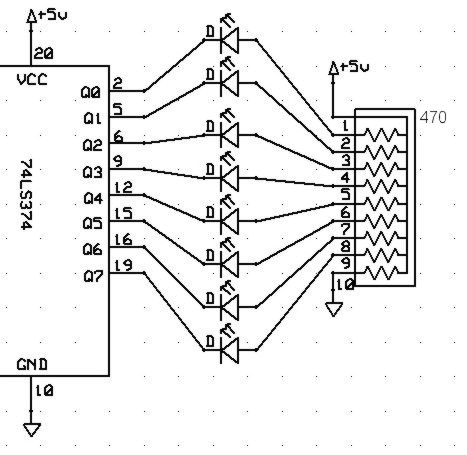
Figure 2: Circuit Output Connections (In the resistor network, each resistor is 470 Ohms. Pin 2 provides D0 to bus, Pin 5 provides D1, etc. Note that 74LS374 labeling of "Q" outputs is in terms of bus bits and not per data sheet for this diagram.)
Spring 2015
IMPORTANT: Lab 2 consists of two independent components (Lab 2 Part A and Lab 2 Part B). Start early! We suggest each of the two students in your lab group be "in charge" of one of the two parts of the lab parts to help divide the work. BUT, we expect both of you to understand and participate in the execution of both labs. And, as always, you must do the pre-labs independently. Please see the course web page for due dates.
Relevant lectures:
- Part A: Lecture 2. Embedded Hardware
- Part B: Lectures 3-4. Microcontroller Instruction Set.
Links to all files referenced in the lab and prelab can be found in the Files section at the end of this document.
Be sure to consult the Lab Writeup Checklist for both the prelab and lab writeup!
Goal: To familiarize you with the operation of the LS374 flip-flop
and understand how it can be integrated into a circuit.
Discussion: This lab focuses on the operation of the ICs used in Lab 2.
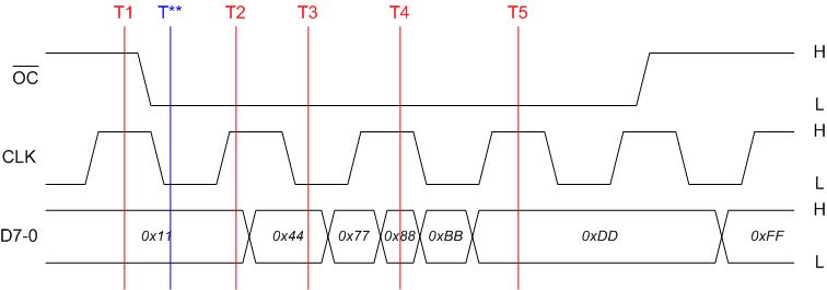
Figure 1: Timing Diagram for Inputs to 74LS374
Figure 2: Circuit Output Connections (In the resistor network, each
resistor is 470 Ohms. Pin 2 provides D0 to bus, Pin 5 provides D1, etc. Note
that 74LS374 labeling of "Q" outputs is in terms of bus bits and not
per data sheet for this diagram.)
Procedure:
None. This section only involves answering questions.
Part A Questions:
A1. (10 points) For Figure 1, list the value of 74LS374 outputs Q7-0 at
each of the times T1-T5 (ignore T**). When you record your answers, use
the conventions described in the discussion section. For example, if Q7
is high, and Q6:0 are low, then your answer would be "0x80" or
"$80" (either notation indicating the number is hexadecimal is
acceptable). The value Z must be used to indicate high-impedance/disabled
output. Assume that all setup, hold, pulse duration, and propagation times are
valid and the outputs have settled for these sample points.
| Time |
Q7:0 |
| T1 |
|
| T2 |
|
| T3 |
|
| T4 |
|
| T5 |
A2. (BONUS: 2 points) If T** occurs 1 ns after the falling edge of CLK reaches zero, and 27 ns after the falling edge of OC reaches zero, what is the value of Q7-0 at T** in Figure 1? Why is it valid or invalid? Limit your answer to 40 words. (Note: you only get credit if you have a correct answer to the "why" question. Look carefully at the data sheet!)
A3. (10 points) Assume the 74LS374 output is connected as shown in
Figure 2. If the inputs described in Figure 1 are applied, compute
the total amount of power consumed by the LED/resistor network (not the LS374)
at each time T1 through T5. Assume the voltage drop across the LED is 1.7
volts. Assume that VOL=0.35V for the LS374. Assume that
the output voltage is quiescent (i.e., it has had time to settle to a constant
value).
| Time |
Power consumed |
| T1 |
|
| T2 |
|
| T3 |
|
| T4 |
|
| T5 |
Goal: To familiarize yourself with the microcontroller assembly
instructions and the process of assembly.
Discussion: This lab focuses on the operation of the CPU core and assembling/dissassembling instructions.
Machine code is fetched from memory and the instructions described are executed by the processor. This includes performing operations (shift, add, subtract, clear) on registers and memory locations and copying values from one location to another.
Procedure:
For each question below, we suggest that you do the work by hand and check it
with an assembler. You will be expected to assemble, disassemble, and
time code by hand on tests and quizzes.
Part B Questions:
B1. (10 pts) Translate the following assembly code into machine
code. The first instruction is done as an example. Do this by
hand using the reference materials. It is OK to use CodeWarrior to check your
work and make corrections after you have done it by hand.
| Assembly instruction
|
Machine Code (hexadecimal values) |
|
LDAA PTT ; read from port T |
B6 02 40
|
| BITA #$80 ; check MSB | |
| BEQ msbUnset ; branch to msbUnset | |
| msbSet: | |
| LDAB #1 ;write 1 to port M | |
| STAB PTM | |
| msbUnset: | |
| LDAA #0 ;write 0 to port M | |
| STAA PTM |
B2. (10 pts) Disassemble the following machine code. Put a brief
comment at the beginning which describes the overall function of the
code. Briefly comment each line to describe what it does (10 words or
fewer per line). For branch instructions, insert labels at the
appropriate locations and use the label values in your disassembled assembly
code. Do this by hand using the reference materials. It is OK to use
CodeWarrior to check your work and make corrections after you have done
it by hand.
| CE 00 00 08 7E 02 40 8E 00 0A 26 F7 20 FE |
Answer Template:
; overall description of the function of the code
______ ______ ;comment
_____:
______ ;comment
______ ______ ;comment
______ ______ ;comment
______ ______ ;comment
_____:
______ ______ ;comment
B3. (10 pts) Determine the values of registers and flags during the
following program. For each instruction, fill in the values that will be
present AFTER the instruction is executed. If an instruction is not
executed, fill in N/A for that row. Do this by hand using the reference
materials. It is OK to use CodeWarrior to check your work and make corrections
after you have done it by hand.
| Assembly Instructions
|
Register D |
Register A |
Register B |
Flags |
||
| Z |
N |
C |
||||
| Initial
Values |
0
|
0
|
0
|
0
|
0
|
0
|
| Value DS.W 1 LDD #1 |
||||||
| STD Value | ||||||
| LDAA #255 | ||||||
| LDAB #255 | ||||||
| ADDD Value | ||||||
| BCC cFlagClear | ||||||
| cFlagSet: CLRA |
||||||
| cFlagClear: BEQ zFlagSet |
||||||
| zFlagClear: CLRB |
||||||
| zFlagSet: LDAB #20 |
||||||
| LDAA #10 | ||||||
| SBA | ||||||
| BPL nFlagClear | ||||||
| nFlagSet: LDD #0; |
||||||
| nFlagClear: LDD #65535 |
||||||
B4. (10 pts) For the program below
, determine the best case execution time by hand, from the
reference materials. For each instruction, indicate the CUMULATIVE number
of clock cycles that will have occurred AFTER each instruction has
executed. If an instruction is not executed, write N/A. Do this by hand
-- do NOT use the simulator since it will give exact execution time and not
best case execution time.
| Assembly Instructions | Cumulative Clock Cycle Count |
|
Initial Value |
0 |
|
LDAA #$0E |
|
| BITA #$80 ; check MSB | |
| BEQ msbUnset ; branch to msbUnset | |
| msbSet: | |
| LDAB #1 ;write 1 to port M | |
| STAB PTM | |
| msbUnset: | |
| LDAB #0 ;write 0 to port M | |
| STAB PTM |
B5. (BONUS: 2 pts) Use the simulator to determine and state the exact
executions time for the programs in both problems 3 & 4 above. Pick an
instruction where the exact execution time differs from the best case execution
time and explain why in one sentence.
B6. (BONUS: 2 pts) Consider the Indexed Indirect example shown in
lecture (Fig 2.6 from Valvano). Create a similar example using different,
non-trivial (e.g., non-zero), data and addresses of your choosing to illustrate
the operation of the instruction: "STX [D,Y]". Include source code
listing and a boxes+arrows figure similar to Figure 2.6 illustrating your
answer. Hand-drawn & scanned black & white figure is OK. Confirm the
operation using the simulator to make sure you got it right, which you need
document only by saying "checked with simulator" in your hand-in.
Goal: To familiarize yourself with the generic writeup hand-in
checklist.
Discussion: It is easy to make small mistakes when you are in a hurry. Using a checklist is your best defense against this in general, and in particular is extremely helpful for avoiding unnecessary point losses when handing in assignments for this course.
Procedure:
C1. Paste a copy of the pre-lab portion of the Lab Writeup Checklist into your hand-in materials. Put a "*" in front of each item to indicate you understand that step. Print a copy of the checklist and put a check-mark in ink next to the "*" when you actually do the hand-in. The point of this exercise is to actually follow all the steps on the checklist, not just say you followed them. Think of how embarrassed you will be if you get something wrong after saying you followed the checklist.
Hand-in Checklist: (66 points + 6)
Part A:
Part B:
Part C:
Refer to the LAB FAQ for more information on lab hand-in procedures and file type requirements. You MUST follow these procedures or we will not accept your submissions.
Goal: Demonstrate that you can read and understand the datasheet for
an IC and use it in a circuit.
Discussion:
This lab uses a flip-flop to hold a data value on a bar graph LED. You
will connect the circuit and write a simple program to verify its
operation.
For this lab, you will adapt the string hash program from lab 1
(lab1_prog1.c). Your new program should be named lab2_prog1_gXX.c
(according to the conventions in the Lab FAQ). Your program shall meet
the following requirements:
Procedure:
| LS374 |
Resistor Network Pins |
||||||||||||||||
| State |
Q1 |
Q2 |
Q3 |
Q4 |
Q5 |
Q6 |
Q7 |
Q8 |
1 |
2 |
3 |
4 |
5 |
6 |
7 |
8 |
9 |
| PB1 unpressed |
|||||||||||||||||
| PB1 pressed |
|||||||||||||||||
| State |
Power Consumption (mW) |
| PB1 unpressed |
|
| PB1 pressed |
Goal: Demonstrate that you can write simple programs in HC12 assembly
language.
Discussion:
This lab uses the same circuit as Lab 2 part A. Refer above for
details on wiring the circuit.
For this lab, you will write a program that uses a loop to add the numbers 1
through 125 and displays the results. Your program shall meet the
following requirements:
Procedure:
Part B.1:
For the questions in part B.1, you may compute the answers using any method
you wish. You do not have to use the assembly program or the
simulator. (Hint: For the questions involving the running sum, you
may find it faster to compute the sum using a formula for an arithmetic
sequence, rather than doing the sum iteratively). The term
counter limit refers to the maximum
value the counter runs to (e.g., 125 in the lab program).
Part B.2:
BONUS: Part B.3:
Part B.1: for procedure part B.1, answer the following questions:
Part B.2:
BONUS: Part B.3:
Goal: To familiarize yourself with the generic writeup hand-in
checklist.
Discussion: It is easy to make small mistakes when you are in a hurry. Using a checklist is your best defense against this in general, and in particular is extremely helpful for avoiding unnecessary point losses when handing in assignments for this course.
Procedure:
C1. Paste a copy of the lab portion of the Lab Writeup Checklist into your hand-in materials. Put a "*" in front of each item to indicate you understand that step. Print a copy of the checklist and put a check-mark in ink next to the "*" when you actually do the hand-in. Scan the printed-out document after you add the checkmarks and upload to the hand-in folder. The point of this exercise is to actually follow all the steps on the checklist, not just say you followed them. Think of how embarrassed you will be if you get something wrong after saying you followed the checklist.
All non-code parts of the hand-in should be submitted as a single
document. Code files should be submitted separately, per the lab FAQ.
Part A:
Part B:
Part C:
Refer to the LAB FAQ for more information on lab hand-in procedures and file type requirements. You MUST follow these procedures or we will not accept your submissions.
Lab 2 Part A
Lab 2 Part B
Lab 2 Part A
Lab 2 Part B
Also, see the course materials repository page.
Change notes for 2015: