Environment/EMC/EMI
Carnegie Mellon University
18-849b Dependable Embedded Systems
Spring 1999
Author: Eushiuan Tran
Abstract:
Embedded systems can exist in environments that are very harsh and noisy, which
can lead to potential problems with electromagnetic interference (EMI). EMI
consists of any unwanted, spurious, conducted, or radiated signals of
electrical origin that can cause degradation in equipment performance. Because
of these problems, all components must comply with specifications to ensure
electromagnetic compatibility (EMC), and there are numerous design methods that
can be used to prevent EMI. During the development life cycle of an embedded
system, the product must be designed to comply with EMC standards, and the
product must also be tested for EMC. In addition, other forms of environmental
reliability testing must also be performed to ensure dependable system
performance in its natural environment. Currently, there is still work to be
done to harmonize various EMC standards to reduce trade barriers between
countries and different use sectors, like Defense and Civilian. Therefore, care
must be taken in developing embedded systems for compliance with the
appropriate standards.
Contents:
Introduction
Embedded systems exist in a wide variety of environments. Because of this,
special care must be taken in developing embedded systems that they can operate
functionally in their intended environment. Many embedded systems exist in very
harsh and noisy environments, which can lead to potential problems with
electromagnetic interference (EMI). EMI consists of any unwanted, spurious,
conducted, or radiated signals of electrical origin that can cause unacceptable
degradation in system or equipment performance. Electromagnetic compatibility
(EMC) is the ability of systems to function as designed, without malfunction or
unacceptable degradation of performance due to EMI withing their operational
environment. Any electrical, electromechanical, or electronic equipment must
not adversely affect the performance of any other equipment or system as a
result of EMI and vice versa. Examples of EMC problems include a computer
interfering with FM radio reception, an operating vacuum cleaner causing
"snow" on TV, a car radio buzzing when you drive under a power line,
an airport radar interfering with laptop computer display, and a telephone
being damaged by lightning-induced surges on phone line. [emclab99] While the
effects of EMI are sometimes minor, like momentary interference on television,
other times the effect may be more catastrophic. For example, a serious
consequence can occur if a signal interferes with the operation of a medical
equipment that was being used to monitor a patient in intensive care. The
origins of EMI are electrical, with the unwanted emissions being either
conducted (voltages or currents) or radiated (electric or magnetic fields). For
EMI to occur, 3 essential elements must exist: an electrical noise (EMI)
source, a coupling path, and a victim receptor. The coupling path from a source
to a receptor can be in 1 of 4 categories: conducted (electric current),
inductively coupled (magnetic field), capacitively coupled (electric field),
and radiated (electromagnetic field). [emclab99] More details will be given
below about the sources and receptors. EMI can occur in 2 different situations:
intersystem EMI and intrasystem EMI. Intersystem EMI occurs between 2 or more
discrete systems while intrasystem EMI occurs between elements in the same
system. [Violette87]
Key Concepts
Sources of EMI An EMI
source can be any device that transmits, distributes, processes, or utilizes
any form of electrical energy where some aspect of its operation generates
conducted or radiated signals that can cause equipment performance degradation.
Figure 1 shows a taxonomy of the different sources of electromagnetic
interference. A brief description of each category will be given below.
[Violette87]
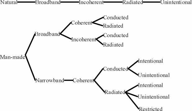
Figure 1: Taxonomy of EMI Sources [Violette87]
- Natural EMI sources - Sources that are associated with natural
phenomena. They include atmospheric charge/discharge phenomena such as
lightening and preciptitation static, and extraterrestrial souces including
radiation from the sum and galactic sources such as radio stars, galaxies, and
other cosmic sources. As shown in the above diagram, all natural sources are
classified as broadband, incoherent, radiated, and unintentional.
- Man-made EMI sources - Sources associated with man-made devices
such as power lines, auto ignition, fluorescent lights, etc.
- Broadband EMI - Electromagnetic conducted and radiated signals
whose amplitude variation as a function of frequency extends over a frequency
range greater than the bandwidth of the receptor.
- Narrowband EMI - Electromagnetic conducted and radiated signals
whose amplitude variation as a function of frequency extends over a frequency
range narrower than the bandwidth of the receptor.
- Coherent broadband signals - Neighboring components of the signal
(in the frequency domain) has a well-defined amplitude, frequency, and phase
relationship.
- Incoherent broadband signals - Neighboring components of the signal
(in the frequency domain) are random or pseudo-random (bandwidth limited) in
phase or amplitude.
- Conducted EMI - Noise signals transmitted via electrical conduction
paths (i.e. wires, ground planes, etc.).
- Radiated EMI - Electric and magnetic fields transmitted through
space from source to receptor.
- Intentional radiating emitters - Emitters whose primary function
depends on radiated emitters. Examples include electronic licensed
communication systems. These include communication, navigation, and radar
systems.
- Unintentional (incidential) radiating devices - Devices that
radiate radio frequencies but is not considered their primary function.
- Restricted radiating devices - Devices that intentionally use
electromagnetic radiation for purposes other than communication or data
transfer. (i.e. garage door operating systems, wireless microphones, etc.)
[Violette87]
Receptors of EMI Any
EMI situation requires not only an emission source but also a receptor. A
receptor is also called a "victim" source because it consists of any
device, when exposed to conducted or radiated electromagnetic energy from
emitting sources, will degrade or malfunction in performance. Many devices can
be emission sources and receptors simultaneously. For example, most
communication electronic systems can be emission and receptor sources because
they contain transmitters and receivers. Figure 2 shows a taxonomy of different
receptors that are susceptible to EMI. Similar to the emission source taxonomy,
receptors can be divided into natural and man-made receptors. A brief
description of each category will be given below. [Violette87]
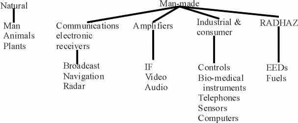
Figure 2: Taxonomy of EMI receptors [Violette87]
- Natural EMI receptors - Natural receptors include humans, animals,
and plants.
- Man-made EMI receptors - Man-made receptors can be categorized into
4 categories: communication electronic receivers, amplifiers, industrial and
comsumer devices, and RADHAZ.
- Communication electronic receivers - These receivers include
broadcast receivers, communication receivers, relay communication receivers,
and radar receivers.
- Amplifiers - Amplifiers include IF, video, and audio amplifiers.
- Industrial and consumer receptors - Industrial receptors include
digital computers, industrial process controls, electronic test equipments,
biomedical instruments, and public address systems and intercoms. Consumer
receptors include radio and TV receivers, hi-fi stereo equipment, electronic
musical instruments, and climate control systems.
- RADHAZ - This category includes radiation hazards to
electro-explosive devices and fuels. RADHAZ is an acronym for RADiation
HAZards, the name given by the U. S. Department of Defense to the program that
is determining the extent of radiation hazards and methods for controlling
them. [Violette87]
EMC Design Considerations
During the design process, engineers must be certain that the system is
designed to comply to EMC standards. There are many design considerations that
need to be taken into account. While it is not the point of this paper to give
detail explanations about EMC design techniques, brief descriptions will be
given simply for an overview. Engineers needing more technical details can
refer to any EMC handbook.
Cable wiring and harnessing is a significant EMI concern. Cables are
required to distribute electrical power and transmit electrical signals for the
operation of various systems. Since cables are usually routed to accomodate its
function, it is often difficult to quantify its environment and it usually
varies over both frequency and electric and magnetic field amplitudes. Cables
can be EMI radiating sources if they act as radiating antennas, or be
susceptible to EMI if they are receiving antennas. Cables can also be coupling
paths. In addition, cables are sometimes harnessed together, so interference
can also be between two cables that are close in proximity. Therefore, their
performance is very difficult to predict. Many specifications classify wiring
or cable types into four to six categories but these classifications are
generally qualitative in nature. More quantitative classifications should look
at levels of power transmitted, or susceptibility of termination. [Violette87]
Connectors are contacts that either link or separate two cables or other
equipments. There may be anywhere from several to hundreds of individual
wire-pins or coaxial sheaths making simultaneous cotact via a connector. EMI
problems from connectors are usually related to poor contact which may result
in arcing, or overheating that leads to arcing. Poor contact connections can
also result in driven-circuit voltage variations from the contact impedence
modulation of the driving-circuit source. Impedence coupling from outside
sources can happen in connector grounding paths. Improperly shielded connectors
or poor cable-connector-equipment- enclosure contact can cause radiated
emission penetration or leaking through apertures. [Violette87]
Grounding is one of the least understood EMC subjects, despite the fact that
it seems straightforward. Improper grounding is the source of many EMI
problems. Grounding is necessary to prevent shock hazard, which occurs when a
wiring or component insulation in an equipement frame or housing breaks down.
Grounding also protects against lightning damage. Grounding is also necessary
to reduce EMI due to electric field flux coupling, magnetic field flux
coupling, and common impedance coupling. There are two reasons why grounding is
not understood well. One reason is that shock and safety control requirements
existed before the electronics and high frequency area, so traditional
grounding techniques were developed to satisfy those requirements. A second
reason is that sometimes a conflict occurs between requirements for safety
grounds and EMI control. [Violette87]
Different considerations must be taken into account with shielding.
Shielding is the use of conductive materials to reduce radiated EMI reflection
or absorption. Usually, the theoretical attenuation offered by materials to
electric, magnetic, and electromagnetic waves does not match that achieved in
practice. This is because a shielded enclosure or housing is not completely
sealed. Any shielding application has some kind of penetrations and apertures
like meter windows, cover plates and access cover members, and push buttons.
These apertures cause leakage and therefore compromises the integrity of the
shielding material. Shielding integrity can be restored through the use of EMC
gaskets, EMC sealants, and conductive grease. Gaskets provide either temporary
or semipermanent sealing applications between joints and structures. Sealants
include conductive epoxies which are used to join, bond, and seal two or more
metallic metaling surfaces, and conductive caulking which is used to shield and
seal two or more metallic mating members held together by other mechanical
means. Conductive grease provides a low-resistivity contact path between mating
members. [Violette87]
The previous design considerations dealt with topics that represent problems
between sources and receptors. There are also EMI control techniques that are
applied at the component, circuit, and equipment levels. The problem with
resistors, inductors, and capacitors is that they do not behave at their stated
values, especially at high frequencies due to the effects of parasitic
inductance and capacitance. Under certain conditions, their performace degrades
at frequencies as low as 1MHz. Inductive devices like transformers, solenoids,
and relays produce low-impedence fields that are sources of EMI if they are
uncontrolled. The main techniques available for controlling transient-producing
devices involves using diodes and filters, and for controlling magnetic fields
involves shielding. Surface tracking is an insulator problem that is a source
of EMI. Surface tracking (or leakage) is a condition in which small currents
creep across the insulator. It is caused by surface contamination of the
insulation by moisture or solid conductive particles. The EMI control technique
is to protect from contamination through the use of proper material and proper
voltage design. Techniques used to minimize EMI in conductors include coating
conductors with a high-permeability material and using hollow conductors at
higher frequencies to minimize external fields. There are many techniques for
different components, not all of which are listed here. This section only
serves as a brief introduction. [Violette87]
Radio-frequency interference (RFI) is a serious EMI problem today due
largely to the large number of radio transmitters that exist. Radio
transmitters range from large, high-power transmitters such as broadcast,
communications, and radar to small, low-power equipments such as handheld
radios and cellular telephones. The problem with radio transmitters is twofold,
as equipment can cause interference to nearby radio and television receivers,
and equipment can be upset by nearby transmitters. Radio and television
receivers can be very vulnerable to RFI pollution from nearby computers.
Repetitive digital signals contain harmonics that can extend into the GHz
range. This unwanted energy can be radiated through cables and wiring acting as
antennas, or conducted through the ac power system. If the levels are high
enough, the receivers can be damaged. It was this emissions problem that caused
countries around the world to pass EMI regulations. In the U.S., complaints
from consumers about interference with television disruption in the 70's drove
the FCC to initiate mandatory EMI testing of personal and commercial computers
in the 1980's. Digital circuits are usually the primary source of emissions,
and analog circuits are more vulnerable to RFI than digital circuits. In
protecting equipment against RFI, it is important to start at the circuit
level. Filters can be used and sometimes multistage filters are needed. Slots
and seams cause the most problem in RFI shielding, so high-quality shields and
connectors are needed for adequate RFI protection. [Gerke94]
Electrostatic discharge (ESD) is also an EMI problem. An ESD event starts
with a very slow buildup of energy, followed by a very rapid breakdown. It is
this fast breakdown that causes EMI problems in modern electronic systems. The
energy discharge yields EMI frequencies in the hundreds of megahertz. The high
speed and frequency of the ESD energy can damage circuits, bounce grounds, and
cause upsets through electromagnetic coupling. The most common method of ESD
generation is triboelectric charging which is caused by stripping electrons
from one object and depositing electrons on another object. In an insulator, it
may be a long time before charge recombination occurs, so a voltage builds. If
the voltage becomes large enough, a rapid breakdown occurs in the air, creating
the ESD arc or spark. Sources of triboelectric charging includes humans,
furniture, and material or device movement. Humidity also affects ESD as the
lower the humidity, the higher the likelihood of ESD problems. High humidity is
helpful because the moisture reduces surface impedance and allows charges to
recombine at a faster rate. However, high humidity leads leads to surface
tracking or leakage at lower temperatures, so there is a tradeoff. ESD has
several failure modes that are not completely independent of one another. These
include direct hit to circuit, ground bounce, electromagnetic field coupling,
and predischarge electric field. Like RFI problems, good protection against ESD
problems start at the circuit level through the use of filters and multilayer
boards. High-quality shields and connectors can be used for good ESD cable
protection. The length-to-width ratio for grounds should be less than 3 to 1.
Thin materials are adequate for shielding and special attention must be paid to
slots and penetrations. [Gerke94]
In addition to the design considerations above, there are other EMC issues
in the design of embedded systems. One is the compatibility among transmitters
that are designed to work together. For example, when every car has a
forward-pointing smart cruise control radar, and they are either next to each
other or coming head-on at each other, the transmitters must be designed that
there is not interference. Another problem to consider is what happens when a
component is inserted in an intergrated system and causes EMI. For example,
computer motherboards are designed with empty slots for different cards to be
plugged into. In particular, video cards are FCC certified to ensure that they
are compatible with whichever motherboard they are plugged into.
There are also issues concerning EMC when humans are the receptors. A scare
that has not yet been proven deals with cellular phone emissions. A source
cited that radiation emitted from cellular phones has shown to cause short-term
memory loss and lapses in concentration. However, this is not a proven fact
yet. There was also an early brain cancer scare with cell phones that actually
led to the FCC limiting the transmitting power of handheld cell phones to 0.3
watts.
Environmental Reliability
Testing
Environmental reliability testing is a systematic approach to the
collection, analysis, and application of information regarding service use in
environmental conditions. Environmental measurement and test became a growing
concern during World War II and the Korean War and a discipline by the Space
Race and the Vietnam War. It is very important that we understand the
interactions of manufactured products and the environmental stresses they
encounter when in use. Environmental reliability testing can be divided into
three categories: development testing, verification testing, and production
testing. Development testing refers to all tests performed generally before the
design goes into production. Verification testing refers to testing performed
on the production configuration. Production testing refers to the application
of environmental stresses to large product populations to improve the
manufacturing process and to verify that it remains under control. Questions to
take into consideration for each type of testing are listed below. [Caruso96]
- How will the product respond structurally, thermally, and in other ways to
environmental stresses?
- What are the strength limits of the product?
- Which materials and manufacturing processes are best suited to the
product?
- Which test setups, fixtures, and stress application methodologies are best
suited to the sought after product information?
- How close do the performance and reliability characteristics of the
product come to design predictions and customer expectations?
- What is the correlation of long-term test results to service life?
- How can the accumulation of fatigue stress be reliabily accelerated
through test compression and exaggeration?
- Which environmental test techniques are best suited to revealing the type
of processing flaws most likely to be present in the product?
- What percentage of the product population should be evaluated to provide
confidence in the robustness of the production process?
- What is the appropriate level of assembly at which to apply environmental
stresses to maximize the likelihood of defect disclosure at the least cost?
- What is the best way to assure integrity of vendor-supplied elements of
the product?
A brief description of the various testing techniques will be presented
below.
- Product characterization - To determine through stress response
surveys how the product will respond structurally, thermally, and in other
relevant ways to environmental stresses.
- Accelerated life tests - Tests that involves applying environmental
stress levels and other conditions that are exaggerated beyond normal service
levels. An example of one test is step-stress or fragility testing where
progressively higher stress levels are applied until the product fails.
- Materials and methodology evaluations - It is important to run
controlled experiments to compare the relative effectiveness of different
materials and assembly processes.
- Test, analyze, and improve tests - Tests where the product is
tested until failure, fixed, and then tested some more. This is a kind of
iterative testing combined with progressive incorporation of test improvements.
- Fatigue/durability tests - Tests that evaluate a product's
long-term performance and survivability through repeated application of
significant environmental stresses for many test cycles. [Caruso96]
- STRIFE testing - a combination of system level stess and life
testing that involves operating conditions exceeding the recommended limits in
order to find weak components. [Siewiorek91]
- Environmental stress sceening - Process used to precipitate
manufacturing defects and infant mortality failures prior to delivery. It uses
increased environmental stresses (i.e. temperature cycling, random vibration,
high temperature) to reveal design defects and process-induced defects.
It is important to note that most product verification tests are usually
one-time tests peformed on a representative sample of the product. Some tests
may degrade the equipment so it is unrealistic to run the test on every single
unit. This raises the issue whether running tests on a representative sample of
the product is a reliable prediction that all of the units will pass the test.
Since you cannot run the test on every single unit, how many units should the
test be performed on to get a good guarantee that all units will pass the test?
Another issue is what kind or levels of design changes requires re-verification
and re-certification? This is always a difficult issue to deal with, but it is
certainly a very realistic concern. There are different points to remember
when choosing environmental reliability tests for the development of any
embedded system. First, there is no universal test procedure. No test will be
completely effective in all environmental situations and each test has its
strengths and weaknesses. The cheapest test is not always the best test as
short-term and long-term tests are optimized for different purposes. There is
no universal test purpose as each test has different goals. Test results are
relative, not absolute. Therefore, test expectations should be realistic.
Lessons from past experiences are also relevant, even if the testing techniques
are obsolete. The purpose and goal of a test should be defined before the test
is performed. Finally, no test can satisfy the goals of the overall testing
process. Tests should be carefully chosen to eliminate nonproductive efforts,
minimize redundancy, and maximize the likelihood of obtaining useful
information. [Caruso96]
Standards Compliance
The ability to sell electronic products depends upon the products being able
to meet the specifications contained in various regulations. Therefore, a brief
study of the different emission standards is necessary. In the United States,
the Federal Communications Commission (FCC) Rules and Regulations, Part 15
Subpart J deals with unintentional emissions from equipment that use digital
techniques and generate or use timing signals or pulses of frequencies in
excess of 10kHZ, or has a pulse rate of 10,000 pulses per second or higher.
These specifications were first formed when users of television and other radio
receivers complained about the interference of radiation from nearby operating
digital devices. FCC 15J defines 2 classes of computing devices that must
conform to emissions specifications. Computing devices refer to any computer
peripheral including modems, printers, and other I/O devices. The 2 classes are
defined as follows:
- Class A: "A computing device that is marketed for use in a
commercial, industrial, or business environment; exclusive of a device which is
marketed for use by the general public, or which is intended to be used in the
home."
Class B: "A computing device that is marketed for use in a
residential environment notwithstanding use in commercial, business, and
environmental environments."
A device that passes Class B limits may be used in a Class A environment. There
are different tests that are required for FCC compliance. There are 3 different
types of FCC compliance as stated in the FCC Rules and Regulations.
- Type approval - Based on equipment examination and test by the FCC.
- Type acceptance - Based on representation and test data for
equipment to be used pursuant to a station authorization. Testing is performed
by the manufacturer and the data is not required unless specifically requested
by the FCC.
- Certification - Based on representation and test data for equipment
designed to be operated without individual license under Rules and Regulations
Parts 15 and 18. Testing is performed by the manufacturer and the test data is
required by the FCC. [Violette87]
The International Special Committee on Radio Frequency Interference (CISPR) is
an organization sponsored by the International Electrotechnical Commission
(IEC). CISPR is composed of each of the national committees of the IEC, a
United Nations commission, and other international unions, commissions, and
committees. It is responsible for setting uniform limits on electromagnetic
emissions from equipment so that trade would not be inhibited between member
countries as a result of different emissions specifications. CISPR publications
deal with inteference for the following items:
- Microwave ovens with power consumption below 5 kW
- Ignition systems
- Televisions, FM receivers, and AM receiver power-line susceptibility
- Conducted and radiated emission of household appliances, portable tools up
to 2 kW, office machines, dimmer regulators, and other electrical apparatus
- Fluorescent lamps
Compliance with CISPR usually varies from country to country and each country
has their own regulations regarding enforcement of the limits. [Violette87]
Currently, there is worldwide effort towards harmonizing various EMC
standards to reduce the trade barriers between countries and various sectors
like Defense and Civilian. The lack of harmonization of standards is a great
burden on manufacturers of electrical and electronic systems because it
increases the duration of the product development cycle and the compliance
evaluation costs. The increased use of these products has made it absolutely
necessary to harmonize various EMC standards. In the Defense sector, the
success of military missions is dependent on the trouble-free field performance
of the electronic and communication equipments used. In the Civilian sector, it
is necessary to protect the radio frequency spectrum from the electromagnetic
noise emission of electrical systems. CISPR has provided recommendations for
the implementation of EMC. However, each country can choose its own set of test
instrumentation, test procedures, and test limits in their own EMC standards.
This causes any manufacturer wishing to supply electronic equipments to
different countries and the Defense and Civilian sector having to deal with a
plethora of EMC standards. [Sampath97]
In Europe, the market unification of 16 countries to form the European Union
has affected the EMC standards scenario. The national EMC standards of these
countries are being combined to form a harmonized EMC standard, called European
Norms. This became known as the EMC Directive which went into effect January 1,
1996. All products that complied to the EMC Directive would bear a CE marking.
This mark was required for any nation that wanted to sell electrical equipment
in the European Community. Compliance can be completed by the following three
ways:
- Self-certification by manufacturer - The manufacturer performs the
tests using in-house test equipment or a commercial test house. After the tests
are completed and documented, the manufacturer files for a declaration of
compliance.
- Technical Construction File (TCF) - The manufacturer prepares a TCF
which decribes the product, sets out the procedures used to ensure conformity
of the product, and includes a technical report or certificate from a Competent
Body which are test facilities designated by member states as able to make
decisions regarding compliance with the EMC Directive. Once the TCF is
completed, the manufacturer files for declaration of compliance.
- Type acceptance - An EC type examination certificate issued by one
of the Notified Bodies is required. Notified Bodies are usually government
agencies in member states.
In the United States, the MIL-STD-461D issued by the Department of Defense
represents a harmonized standard for military equipments and subsystems.
Even with all the work that has been done to harmonize EMC standards, there
are still more than 20 European Norms on EMC, various MIL-STD-461 documents,
different FCC Rules and Regulations parts, and other EMC specifications from
different industries. This still results in problems including different test
requirements and different limits and units of measurements. Currently, 5
certification bodies in the world, North America's Underwriters Laboratories
(UL), Germany's VDE, Italy's IMQ, the UK's BABT, and the TUV Product Services
have teamed up to issue an international EMC mark to products that meet all of
the standards followed by the major economies. Even though acquiring this
international mark requires product testing to comply to each standard and a
high bill toward testing charges, it is a good step toward achieving a global
EMC compliance certificate for a product. [Sampath97]
Available tools, techniques, and metrics
EMI testing is needed because EMI predictions and analysis alone are inadequate
to assure compliance with EMI regulations. It is also necessary due to the
complexity of design for EMC. There are a number of methods and nomenclature
used in measuring EMI emission and susceptibility characteristics of equipment
and subsystems. There are three levels of testings that exist and generally,
the higher the level of testing, the more difficult and expensive it becomes.
- Low-level testing - Component, equipment, and subsystem testing.
Basically, low-level testing ensures that there will be very few EMI problems
when testing at the next higher level.
- Intermediate-level testing - System and vehicle testing. This
involves testing for EMI degradation or malfunction due to self-jamming.
- High-level testing - Electromagnetic environment (EME) interaction
with the test item. Even after low-level and intermediate level testing,
numerous problems can occur when the product is operating in its natural
environment. [Violette87]
EMI testing can also be divided into three categories - compliance,
engineering, and audit testing.
- Compliance tests - These tests are run to prove that the design
meets appropriate EMI requirements. These tests require very precise and
absolute measurements, so expensive equipment and experienced personnel is
needed. Compliance testing is performed at the end of the design but before
sale of the product. Testing can be performed either using an independent EMI
test laboratory or an in-house EMI test laboratory.
- Engineering tests - The objective of these tests is to uncover
potential problems early in the design process. This is when you have the most
time and flexibility in making design changes. Unlike compliance testing,
engineering testing does not require high precision and accuracy to obtain good
results, so simple tests with inexpensive equipment is satisfactory. EMI
engineering tests are performed in-house. Some tests include emission
prescreening, ESD prescreening, RFI prescreening, and power-disturbance
prescreening.
- Audit tests - Audit tests are associated with manufacturing and
quality, not with design. The goal of audit testing is to ensure that the
design stays intact through its product life. An example of audit testing is
statistical checks, where a unit is occasionally pulled off the production line
and run through a series of EMI tests. Screening tests on all production units
can prevent faulty units from leaving the production plant but it can be very
expensive. [Gerke94]
Relationship to other topics
Conclusions
There are several important conclusions to take away from this section. Mainly,
they are the following:
- EMI is a major problem in the development of embedded systems. Since
embedded systems often exists in very noisy environments, even more attention
must be paid to EMC.
- EMC must be taken into consideration during the design stage. Designing
for EMC is a long process that starts early in the life cycle and proceeds
through the testing stage and even in the post-production stage. Therefore, EMC
is a concern for engineers at all phases of the developement of an embedded
system.
- Environmental reliability testing is used to eliminate potential problems
that the system can experience when it is operating in its natural environment.
- There are many EMC standards used in the regulation of products that may
cause EMI.
EMC is a very important issue that embedded systems designers have to deal
with. Even though it is a very difficult topic, there are may practical design
techniques that can be used to design for EMC. This will greatly assist
designers who are unfamiliar with EM theory to be confident in their design for
EMC.
Annotated Reference List
- [Caruso96] Caruso, Hank, "An Overview of Environmental Reliability
Engineering," Proceedings of Annual Reliability and Maintainability
Symposium, Las Vegas, NV, 1996, pp. 102-109.
This paper presents an overview of different testing techniques used in
environmental reliability engineering.
- [Gerke94] Gerke, Daryl and Kimmel, Bill, "ESD as an EMI problem ...
how to prevent and fix," EDN's Designer's Guide to Electromagnetic
Compatibility, vol. 39, no. 2, January 20, 1994, pp. 23-32.
This paper gives an overview of what is ESD, the EMI problems related to ESD,
and how to prevent these problems.
- [Gerke94] Gerke, Daryl and Kimmel, Bill, "Radio-frequency
interference ... why computers and radios hate each other," EDN's
Designer's Guide to Electromagnetic Compatibility, vol. 39, no. 2, January
20, 1994, pp. 33-40.
This paper gives an overwiew of what is RFI, the EMI problems related to RFI,
and how to prevent these problems.
- [Gerke94] Gerke, Daryl and Kimmel, Bill, "EMI testing ... if you wait
until the end, it's too late," EDN's Designer's Guide to
Electromagnetic Compatibility, vol. 39, no. 2, January 20, 1994, pp.
101-108.
This paper describes the different categories of EMI testing which are
compliance testing, engineering testing, and audit testing.
- [Sampath97] Sampath, K., Subramanian, C., and Das, Sisir K.,
"Harmonization of International EMC Standards," Proceedings of the
International Conference on Electromagnetic Interference and Compatibility,
Chennai, India, 1997, pp. 127-132.
This paper discusses the EMC regulation harmonization efforts performed by
different countries.
- [Siewiorek91] Siewiorek, Daniel P. and Koopman Jr., Philip John, The
Architecture of Supercomputers - Titan, A Case Study, San Diego, CA: Academic
Press, Inc., 1991.
Contains explanation of STRIFE testing.
- [Violette87] Violette, J. L. Norman, White, Donald R. J., and Violette,
Michael F., Electromagnetic Compatibility Handbook, New York: Van
Nostrand Reinhold Company, 1987.
This is an EMC handbook intended for engineers and technicians working with
electrical and electronic equipment.
- [emclab99] http://www.emclab.umr.edu, University
of Missouri-Rolla Electromagnetic Compatibility Laboratory, accessed April
14, 1999.
This website contains general EMC-related information, information on EMC
modeling tools, and information about the work done at the EMC Laboratory at
the University of Missouri-Rolla.
Further Reading
- Gerke, Daryl and Kimmel, Bill, EDN's Designer's Guide to
Electromagnetic Compatibility, vol. 39, no. 2, January 20, 1994.
A special supplement to EDN magazine. The audience of this supplement is
practicing engineers who need to understand about EMC but have little
background in the area. The focus is on practical insights and ideas about EMI
that will help the engineer to identify, solve, and prevent EMI problems in
their design.
Loose Ends
Go To Project
Page