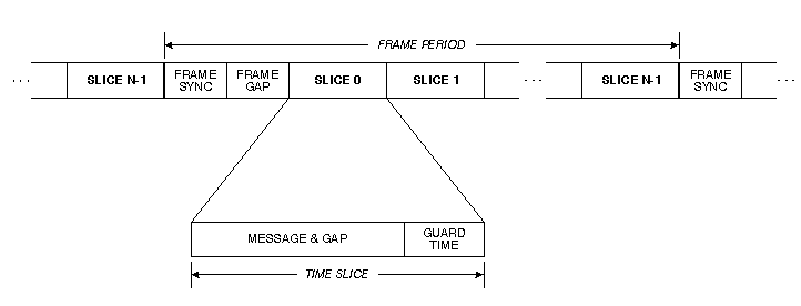
Figure 1. TDMA timeline.
United
Technologies Research Center
June 30, 1995
UTRC Technical Report RR-9500470
Time Division Multiple Access (TDMA) protocols have the potential to provide simple but effective broadcast bus communications for embedded systems. However, bus-master based protocols such as TDMA can be undesirable in practice because the bus master node constitutes a single-point failure vulnerability and adds to system expense. We present the Jam-TDMA (J-TDMA) protocol, which eliminates the need for having a bus master through the use of a nondestructive jamming signal for frame synchronization. We give a detailed description of the J-TDMA protocol and show how to minimize the effects of speed differences among nodes on TDMA systems, which can be critical for low-cost implementations. We believe that J-TDMA reaps the benefits of TDMA protocols without suffering the reliability and system complexity drawbacks of other TDMA methods.
Index terms: broadcast bus communication networks, time division multiple access, multi-access protocols
In this paper we discuss Time Division Multiple Access (TDMA) protocols used in broadcast bus communications for embedded systems. TDMA protocols have the potential to be both simple and effective for embedded system applications. In particular, TDMA is at its best when providing highly efficient use of bandwidth for a well characterized, periodic communication traffic workload as found in many embedded systems. Additionally, the simplicity of TDMA lends itself well to embedded systems with limited hardware resources at each node. TDMA also avoids many subtle failure modes associated with more complex protocols, such as duplicate tokens on token bus systems. TDMA can have low protocol overhead if the multiplexed time slices are well balanced with respect to node workloads. And, TDMA does not require collision detection circuitry, which can be difficult or costly to implement in embedded systems.
Unfortunately, it is often difficult to actually use TDMA in practice because of reliability and cost concerns. As described later, classical TDMA uses a single bus-master node to synchronize communications. In many embedded systems, single points of failure are unacceptable; this is true not only in military and avionics systems, but also in many commercial systems, such as elevators and automobiles. Furthermore, a bus master increases size, weight, power consumption and cost. Alternatives to a single bus master seem to simply push complexity comparable to the master node into slave nodes.
The key problem with using TDMA in practice is the need for a physical or logical bus master. This seems to have in practice limited TDMA to those applications that have a natural bus master, primarily satellite communications.
We shall show a way to implement TDMA without using a bus master of any kind. Our technique permits nodes to come on-line and off-line freely, and is accomplished with a minimal increase over the logic complexity of slave nodes over classical TDMA. We feel that this will greatly increase the attractiveness of using TDMA to provide both simple and reliable embedded communications.
Before presenting our new TDMA-based protocol, we first review classical TDMA, then discuss previous solutions to the problems caused by having a bus master.
In TDMA, bus access is controlled using a frame-based approach. As shown in Figure 1, transmissions on the bus are grouped into frames. Each frame starts with a frame sync, which is a unique bit pattern transmitted by the bus master. A frame gap following the frame sync is required with some transmission technologies (e.g., transformer coupling) to allow time for the bus master's transmitter to return to a quiescent state.

Figure 1. TDMA timeline.
The frame gap is followed by N time slices. In the simplest case, one time slice is assigned to each of N slave nodes. When a frame sync is detected by a slave node, that slave node starts a countdown timer that expires at the start of its uniquely assigned time slice. When a slave node's time slice arrives, it transmits a message. In some implementations a gap period after the message is required to allow the transmitter to return to a quiescent state. After the message and gap, a guard time is allocated to accommodate timing skew among the oscillators of the nodes.
When all time slices have elapsed, the bus master transmits another frame sync message to restart the cycle. This frame sync serves as a central time reference point and is used to resynchronize the time bases of each slave node, eliminating cumulative time skew caused by oscillator speed inaccuracies over the duration of a frame. If a slave node has nothing to send during its time slice, or the slave node is off-line, its time slice elapses unused. There are several possible elaborations on this arrangement, such as allocating multiple time slices to nodes with heavy communication workloads (e.g., [6]), and truncating unused slices (e.g., [4]).
All previous implementations of TDMA seem to use either a permanent or transient bus master of some kind. Unfortunately, use of a bus master tends to introduce complexities and costs that detract from TDMA's advantages. Before proposing a solution, we shall review what we believe to be the common approaches to dealing with bus mastership in TDMA: static allocation of mastership, dynamic allocation of mastership, and initial allocation of mastership with stable time bases.
Static allocation of bus mastership is the classical TDMA approach [6]. In the simplest case, a dedicated bus master is used. An alternative is to replicate the extra logic for mastership within at least one slave node, then designate that node as both a slave and the bus master. For example, node 0 could always be the bus master. The problem with static allocation is obvious: whether the bus master is dedicated or combined with a slave node, failure of the bus master causes network failure.
An alternative scheme is to designate a bus master among the operational slave nodes during network initialization. Thus, rather than statically designating a particular node as the bus master, the first node to be turned on could become the bus master. Once a bus master takes control, it remains in control until it fails. If a bus master fails, another slave node may detect the failure and become bus master itself (a similar idea is described in [7]).
The problem with dynamic allocation of mastership is that if two nodes are turned on almost simultaneously (within one bus propagation delay Τpd), a conflict arises. Some arbitration mechanism must be invoked that designates one, and only one, bus master before proper network operation can proceed. This arbitration mechanism increases slave node complexity, and seems a high price to pay for a function that is only used when the system is reset. The arbitration mechanism is often complicated by the fact that collision detection circuitry is not available due to cost and practicality constraints.
Even with dynamic allocation of mastership, the current master still constitutes a single point of failure. If extra logic is included to facilitate automatic network resets and redesignation of a bus master, single-point failures can be minimized. However, the resultant node design is much more complicated than the original TDMA slave node.
A somewhat different approach is taken by the ARINC-629 protocol. [4] In ARINC-629, there is no single bus master during normal operation. Rather than using a frame sync from a bus master, each node keeps track of time slices as they elapse, whether there are transmissions or not. Frame starts are not explicitly delineated by transmission events. In order to limit the effects of accumulated time-base skew between nodes, two cross-checked time sources are incorporated into each node, and nodes resynchronize at the end of every transmitted message. ARINC-629 implementations must ensure that messages are sent occasionally to avoid excessive timing skew, even with redundant oscillators at each node.
With ARINC-629, there must still be some initial synchronization event to start operation. This is done with an arbitration scheme that must deal with potential message collisions, just as in the case of dynamic allocation of mastership. The difference with the use of stable time bases is that after the initial master gains control (by issuing a non-colliding message that all other nodes synchronize to), mastership is then irrelevant for further operation.
The disadvantages of initial allocation of mastership with stable time bases are that logic for an initial arbitration scheme must be included, and very stable time bases must be used to minimize oscillator skew over the longest possible time between messages on the network. One could reduce the effects of oscillator skew by generating dummy messages periodically, but such messages would have to be sent sparingly to gain the benefits of ARINC-629's variable-width time slice feature that compresses unused time slices to increase efficiency. A dummy message scheme would also resemble a dynamically allocated master arrangement, with the attendant complexity increase and failure modes. A further problem with using stable time bases instead of frame syncs is that if a node is reset or brought on-line after the bus has started operation, there is no predictable reference for determining where the newly activated node's time slice begins; and no guarantee of how long the newly activated node will have to wait before some recognizable signal is transmitted by other nodes on the bus.
In order to avoid the problems of other TDMA protocols, we propose a new scheme that completely eliminates the need for a bus master. Because the protocol is based on using a "jam" signal as the frame sync, we call it J-TDMA.
Classically, a TDMA bus master's frame sync is used to avoid collisions among slave nodes by limiting accumulated timing skew. This resynchronization at the start of each frame, combined with a guard time at the end of each time slice, prevents slave node transmissions from overlapping. Typically, the frame sync signal consists of a unique waveform pattern such as an intentionally misplaced signal transition edge or a long sequence of ones that is otherwise illegal in a bit-stuffed transmission scheme.
The reason that collisions are undesirable in TDMA is that they are difficult or expensive to detect. If two transmitters were to attempt to send frame syncs concurrently, they might be enough out of phase to cause waveform interference between high and low physical signal levels on some or all of the bus as their signals propagate. This interference could cause some receivers to miss some or all of the frame sync message. Even on systems where such interference might not be a problem at the physical level, TDMA designs traditionally designate a bus master.
The key idea of J-TDMA is to use a nondestructive frame sync signal, so that more than one transmitter can send a frame sync without adverse interaction among signals. While most other TDMA protocols focus on having a single bus master issue frame syncs, J-TDMA is designed to tolerate multiple overlapping frame sync transmissions. Thus, the issue of establishing a unique bus master is rendered moot in J-TDMA.
An excellent candidate for such a frame sync signal corresponds to a "jam signal" used to enforce recognition of collisions in collision-based protocols (e.g., [2]). For example, in a baseband multimode fiber optic system, one or more transmitters can jam by emitting light (baseband "on") for a period of several bit times. As another example, current-mode transformer coupled systems can jam by having one or more transmitters assert a physical "high" value for longer than a bit time. In general, any signal which nondestructively propagates throughout the communication medium can serve as a jam signal. No data need be communicated by the jam signal -- only the presence of a jam signal need be detected in order to establish a synchronization event.
Detecting a jam signal is inherently easier than detecting a collision, because during jamming all transmitters are asserting mutually non-destructive waveforms, whereas during a collision between arbitrary data transmissions the waveforms may destructively interfere. Care must be taken to ensure that communications bus noise is unlikely to falsely trigger jam detection; in most cases this simply means that the jam signal must be longer than a bit time rather than shorter.
A jam signal is not the same as a "bit dominance" signal such as that used by the Controller Area Network (CAN) protocol.[1] In bit dominance a transmitter broadcasting a logical "1" must dominate over some other transmitter broadcasting a logical "0". For jamming, it is sufficient that transmitters not interfere with each other while each is broadcasting only a "high" level. So, bit dominance may be used to implement jamming, but jamming does not require a full bit dominance capability.
Once we decide to use a jamming signal as the frame sync, all questions of establishing a unique bus master disappear. It is perfectly acceptable for multiple nodes to be designated as bus masters and issue overlapping frame sync signals, because they won't interfere with each other; only a single elongated frame sync will be detected by any receiver on the bus. Furthermore, issues of implementing an arbitration mechanism to momentarily pick a bus master (as in the case of ARINC-629) also disappear. There truly never needs to be a unique bus master, because all nodes can assert frame syncs without concern for collision.
J-TDMA follows the same time sequence shown in Figure 1 for TDMA. The major difference is that more than one node may issue overlapping frame sync signals. Figure 2 gives a Finite State Machine (FSM) diagram for the logic contained in each node when implementing J-TDMA. In the description we shall use "frame sync" to mean the logical operation of establishing a time reference, and "jam" to mean the physical act of transmitting a jam signal to implement a frame sync operation.
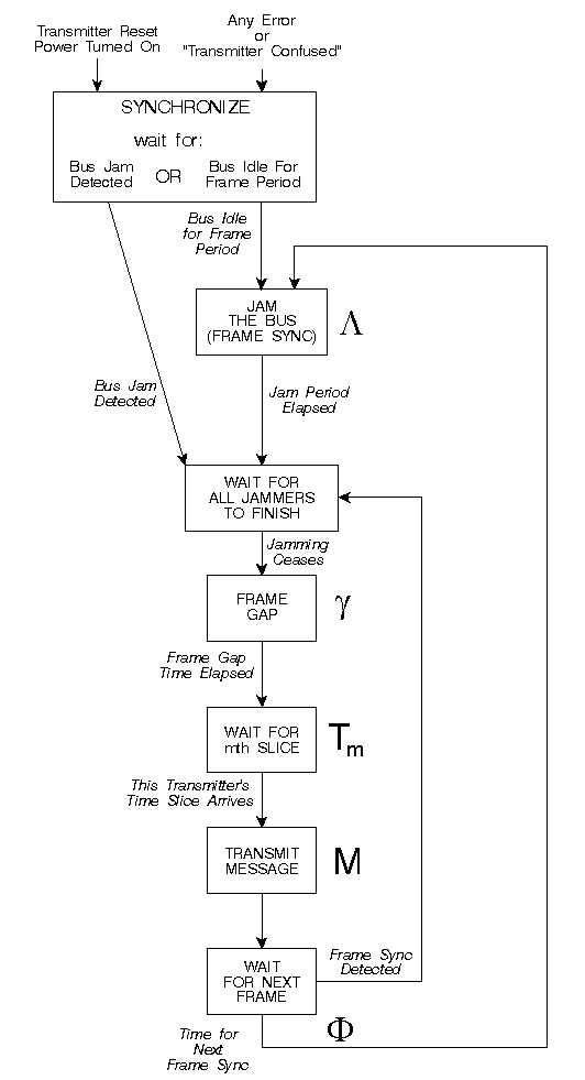
Figure 2. Finite State Machine for J-TDMA protocol.
Initialization is handled by having each newly activated node wait for an entire frame period to determine if the network is active. If a frame sync is detected, the node joins the active network. If no signals are detected for an entire frame period, then the node is the only active node on the bus, so it asserts a frame sync to start bus operation. It is permissible for multiple nodes to assert this first frame sync without arbitrating for initial mastership, because multiple jammers are allowed.
In normal operation, each node waits for its assigned slot interval beyond the frame sync, and sends a message at the appropriate time. It then waits until the anticipated end of the frame time, then emits a frame sync. If a node detects a frame sync before its computed end of frame time, it simply accepts the incoming frame sync signal as the start of a frame without emitting its own frame sync. It is possible that multiple nodes will start transmitting frame syncs within a propagation delay of each other, because they won't receive other frame syncs until up to a propagation delay after other nodes assert them. With this method, the nodes with fast oscillators will assert frame syncs, while other nodes resynchronize to them. As nodes come on-line and off-line, and components age, the fastest operating nodes will set the frame period.
In all fairness, JTDMA still has a potential single-point failure mode: jabbering. If a single node transmits a continuous jamming signal or data transmission, other nodes will be prevented from using the communication bus. However, this failure mode is inherent in any shared-medium communications scheme, and so is no worse a problem than that found in other media access protocols.
Now that we have described the protocol, we shall turn our attention to deriving equations to describe the various parameters that must be used to actually implement the protocol. We shall start by assuming that oscillators are highly accurate as a way of illustrating the effects of propagation delay on synchronization. In the next section we shall augment the equations with factors that account for oscillator skew found in real systems.
In systems using highly accurate oscillators, calculating the parameters of interest is relatively straightforward. In all cases we assume that computational delays at each node are negligible. Table 1 is a summary of our notation. All times are considered to be measured at each individual node unless otherwise noted.
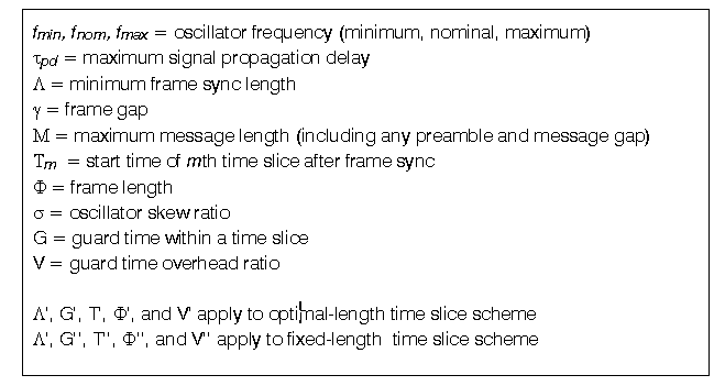
Table 1. Summary of notation.
The minimum frame sync length Λ, measured at node m, must account for a 2τpd worst case round-trip time in order to guarantee that potential signals from all jamming nodes (which can be skewed in starting time by up to one propagation delay) have time to reach all receivers (requiring a second propagation delay). This minimum jamming period ensures that the jamming will be received as an uninterrupted waveform at all receivers without gaps caused by skewed jam starting times.

We define the minimum time to the start of the mth time slice Τm, to be measured, at node m, from the end of the collective frame sync waveform. Therefore, Τm must take into account the frame gap length γ, and maximum message length M allowed within the system. There will be up to one τpd skew between nodes resulting from the travel time of the frame sync signal. Another τpd is required to prevent collision between the end of one message and the start of the next message caused by propagation delay between successively transmitting nodes. Both τpd terms must be added into each time slice so that every pair of transmitters has a 2τpd gap between transmissions; this accommodates the case where the transmitter that was first to jam (from a global perspective) is followed in transmission by the transmitter that jammed just short of a τpd later (also from a global perspective) where the two transmitters are at opposite ends of the communications bus.

The frame period Φ, measured at node m, is simply Λ plus the time of the start of the Nth time slice (where the highest transmitter number is N-1):

In all real communication systems, the oscillator at each node operates at a slightly different frequency than the oscillators at other nodes. Most current systems, including TDMA systems, are relatively insensitive to slight inaccuracies in oscillator speed in normal operation. This insensitivity stems from the use of commonly available, high accuracy crystal oscillators (e.g., +/-0.01% or better), and operation at moderately high data rates (e.g., 1 Mbit/sec), resulting in a small cumulative skew between resynchronizations.
As distributed microcontrollers become more common in embedded systems, there will be cost pressure to accommodate significant amounts of time skew caused by use of less expensive crystal oscillators (e.g., +/-0.1% or worse), relatively inaccurate RC-based on-CPU oscillators (e.g., +/-10% or worse), and slower data rates over inexpensive communication channels. In order to address these issues we explicitly include skew introduced by oscillator speed inaccuracies in the following equations. Again, all times are measured independently at each individual node m.
We use a skew parameter, σ, to compensate for the differences among oscillator speeds within the communications network. The strategy used is to make all time delays long enough to accommodate the worst-case skew between any pair of nodes, thus avoiding overlapped transmissions (except during frame sync, when it is used to ensure overlapped transmissions without gaps). We define the oscillator skew ratio σ to be the inaccuracy of the oscillator:

where the nominal system frequency (fnom) may vary to be as fast as (fmax) or as slow as (fmin) as specified by the oscillator manufacturer for expected system operating conditions. Specifications in real oscillators are typically given as nominal operating frequency combined with a skew percentage, leading to a slight asymmetry in skew ratios between the worst-case fast and slow oscillators. We assign σ the slightly higher value of the two (while we could have defined σ as the ratio of the maximum to minimum frequency, this definition would have been at odds with data sheet specifications).
The minimum frame sync length Λ' must account for the possibility of some nodes having fast oscillators, and so uses the skew parameter σ to extend the length of the frame sync, ensuring that a small gap in the jamming waveform is not caused by oscillator speed differences. The minimum frame sync length Λ' is given by:

The start of the mth time slice Τm', must use the skew factor σ to account for the different oscillator speeds at different nodes, because each node measures slightly different times for the frame gap and time slices. For convenience, we define α as:

α accounts for σ with a scaling factor of 2 to ensure that a node with a fast oscillator (σ times faster than nominal) does not start a message conflicting the end of a message from some preceding node with a slower oscillator (σ times slower than nominal). The range restriction on σ ensures physical realizability of the following equations. If σ is close to 3/2, skew time will account for most of the network bandwidth, and the system will be impractical.
Now we define the guard time, Gm', required for each time slice as:

This definition of guard time accounts for both the oscillator skew up to the start of the mth time slice, skew during the message (with 2τpd included as in Equation 2), and skew that occurs during the Gmth guard interval itself. Based on this guard time definition, we can iteratively define the start of each time slice Τm' as:

The first time slice starts after the frame gap (and associated skew). The start of each time slice is delayed by increasingly long guard times as skew accumulates throughout the frame time. This has a closed-form solution of:

The frame period Φ' is simply the frame sync Λ' plus the time of the start of the Nth time slice (where the highest transmitter number is N-1):

This value of Φ' is optimal in the sense that it is the shortest possible frame period that safely accommodates worst case oscillator skew. We define the guard time overhead V' of this method to be:

V' provides a measure of the effect of skew on overall system efficiency.
While the value of Φ' from the preceding section is optimal, this value may be difficult to achieve in practice, because it results in each time slice in the system being a different length (larger values of m are later in the frame, have more accumulated skew, and thus a longer guard time). It is easier to implement and perform configuration management on systems where the size of each time slice is constant (as in the traditional TDMA scheme). Therefore, we derive the equations for constant-size time slices below. Once again, all times are measured independently at each individual node m. A comparison of optimal-size slice vs. constant-size slice efficiency is given in the next section.
The starting time of the mth time slice, Τm'', is simply the sum of m constant-length time slices and the frame gap:

where the guard time G'' for each constant-width time slice must account for accumulated skew over all N time slices plus the skew that accumulates during the guard time of each slice:

and the frame length Φ'' is:

Finally, we define the guard time overhead V'' of this method to be:

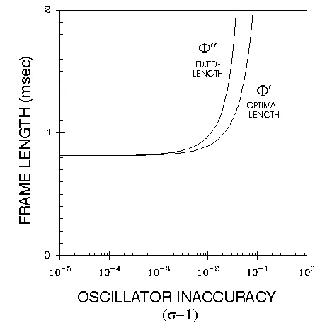
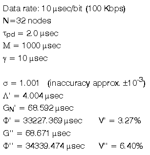
To illustrate the effects of limited oscillator precision and resultant skew, Examples 1 and 2 show two representative system designs.
Example 1 is representative of a relatively fast, small system with moderately stable oscillators. The maximum guard time is less than a bit length, and guard time overhead is well under one percent. In many real systems, oscillators are typically better than 1 part in 104, or a worst-case oscillator can be replaced with one not quite so bad. Also, temperature is relatively uniform across nodes, and system lives are moderately short, limiting aging effects. So, in many cases, design engineers can ignore oscillator skewand still have a system that works most of the time.
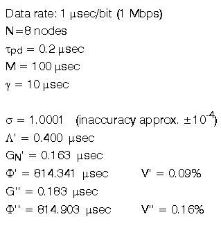
Example 1. Example system with small guard time.
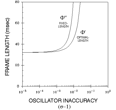
However, Example 2 shows a situation similar to one we have encountered in practice. In this example the bit rate is much slower (because of the use of inexpensive twisted pair wires), and τpd is much longer because it is a physically large installation. Most critically, σ is worse because nodes are physically separated and exposed to different and varying operating conditions, the system life is extremely long, and less precise oscillators are used when possible to reduce system costs. In this case the guard time must be almost 7 bits long for proper operation, so it is unlikely that this system would be manufacturable without calculating and allowing for a guard time. The overhead for optimal-length time slices (V') is approximately half the overhead for fixed-length time slices (V''). Using optimal-length time slices saves more than a millisecond per frame of overhead, which is roughly equivalent to one message per frame bandwidth improvement. And, as shown by the graph, the efficiency savings would increase dramatically with even slightly higher levels of oscillator inaccuracy.
Example 2. Example system with large guard time.
We have developed an SES/workbench model [5] to simulate a J-TDMA network. In particular, the model accounts for signal propagation delays along the bus and models time skew among nodes having different speed oscillators. The simulation also detects any unintentional collisions among node transmissions.
We do not report simulation throughput and latency results here, because the behavior of TDMA networks is well known (e.g., [3]). Rather, the purpose of the model was to help us validate the finite state machine and equations. The equations presented have been tested via simulation, including checking optimal-length time slices to verify optimality. Understanding and properly accounting for of clock skew and propagation delay effects was harder than we anticipated; the simulations proved a valuable tool in furthering our understanding of skew effects.
Because J-TDMA is an improved frame synchronization mechanism for TDMA, most techniques for improving TDMA performance also apply to J-TDMA.
More efficient use of the bus may be made by assigning multiple time slices to nodes with heavy workloads. For example, if one node transmits twice as many messages as any other node, it may be assigned two slices instead of one. Of course this technique results in a minor increase in node logic complexity.
Another efficiency improvement technique is to use time slice compression, as done in ARINC-629. With this scheme, if a time slice goes unused for a predetermined period of time shorter than the entire slice time, all nodes automatically progress to the next time slice without any signaling taking place. This scheme compresses unused time slices to improve efficiency. In this case, the frame period varies with the number of messages actually transmitted.
This paper has introduced a new communications protocol, which we call J-TDMA. By using a jamming signal, one or more nodes may assert frame sync signals without destructively interfering, eliminating the need for a bus master. Arbitration to select a transient bus master for bus initialization is similarly avoided. We have also derived equations for system parameters that account for variations in oscillator accuracy, enabling implementors to build systems with less accurate, less expensive time bases. We believe that our results show how to build significantly simpler and less expensive TDMA systems, while at the same time permitting more flexible and robust system design.
The authors wish to thank Alan Finn of UTRC for his technical and editorial contributions.
[1] Robert Bosch GmbH (1991), CAN Specification, Ver. 2.0, Stuttgart, Germany, September.
[2] P. Gburzynski & P. Rudnicki (1989) A virtual token protocol for bus networks: correctness and performance, INFOR 27(2): 183-205, May.
[3] H. W. Lee & L. Liang (1990), A Generalized Analysis of Message Delay in STDMA, Computer Networks and ISDN systems, 19(1), September.
[4] National Semiconductor Corp. (1992), ARINC 629 Communication Integrated Circuit Data Sheet, Rev. 2.0.
[5] Scientific and Engineering Software, Inc. (1992), SES/workbench Reference Manual Release 2.1, Austin, Texas.
[6] W. S. Stallings (1991), Data and Computer Communications, 3rd ed., Macmillan, New York.
[7] G.J.W. van Dijk & A.J. van der Wal (1989), Performance measurements of a communication protocol implemented for distributed real-time systems, In: Proceedings of the 14th Conference on Local Computer Networks, IEEE Computer Society, 307-314.
Note: at the time the HTML was written, greek typesetting was not available for testing -- I went by the proposed HTML-3 specification. Hard-copy of the paper will be U.S. Mailed upon request.
Phil Koopman -- koopman@cmu.edu